
Process Flow Diagram For Coal
UDC 662 . 76 Development of Coal Partial Hydropyrolysis ...
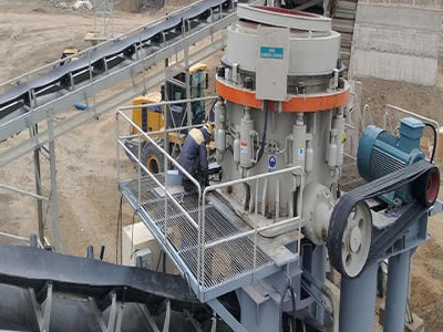
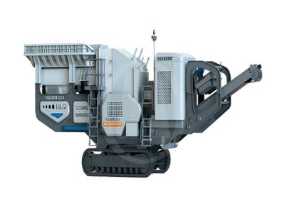
composed of a reformer and a partial oxidizer, process verifiion tests were carried out using a 1t/d process development unit (PDU). Test method Fig. 4 shows the process flow diagram of the PDU, and Photo 1 is an overall view thereof. Pulverized coal injected through burners

CASE STUDY ON THRESHOLD PROBLEM Sponge Iron Production ...
Sponge Iron Production Process Process description This is the case study of typical coal based sponge iron plant of 500 tonne per day capacity. The process flow diagram (PFD) of the sponge iron process is shown in Fig. 1. Different streams in the PFD are .
Oil Industry Process Flow Diagram
Oil Industry Process Flow Diagram. Create Process Flow Diagram examples like this template called Oil Industry Process Flow Diagram that you can easily edit and customize in .


What is Process Flow Diagram? • Panorama Consulting ...
04/05/2018 · A Process Flow Diagram (PFD) demonstrates the relations between significant segments in a framework. PFD likewise arrange process configuration esteems for parts in various working modes, commonplace least, ordinary and greatest. A PFD does not demonstrate minor segments, funneling frameworks, channeling appraisals and assignments. They use a series of symbols and notations to .


VMOST Analysis | Process flow diagram, Analysis, Block diagram
Jul 16, 2020 The VMOST structure and analysis process can be applied to a program or project effort itself in order to help define the project mission and objective, as well as the strategy and tactics the project will undertake to achieve them, and ensuring that they are all aligned. #VMOST #Structure #VMOSTStructure #AnalysisProcess #StrategyTactics #Template #Canvas #Diagram #Creately

Process Description and flow diagram of Coal Based DRI Plant
07/08/2016 · Process Description and flow diagram of Coal Based DRI Plant Description of Sponge Iron Manufacturing Process Most of the plants in India use DRI process—a solid state direct reduction process by which iron ore is reduced to sponge without phase change.


USB2
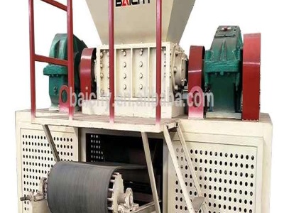
A multistage process for drying coal in which coal is passed into a first fluidized bed reactor at a temperature of 300 to 550 degrees Fahrenheit, air is fed into the first reactor in order to maintain the density of the fluidized bed at from 20 to 50 pounds per cubic foot, and from about 40 to about 60 percent of the water from the coal is removed from the coal and the first reactor.


Process Flow Diagrams COAL TO OLEFINS (CTO) / METHANOL .
14 Process Flow Diagrams — Coal to Olefins (CTO) / Methanol to Olefins (MTO) Highpressure black water flashing valve Highpressure black water flashing valve Synthesis gas venting control valve Black water onoff valve Black water onoff valve Valve Appliion in Gasifiion Process (Coal Slurry)


Diagrams for Understanding Chemical Processes by ...
02/10/2020 · This block flow plant diagram is for a coal to higher alcohol fuels plant. Clearly, this is a complied process in which there are a number of alcohol fuel products produced from a .


Draft Guidelines for the Assessment of Former Gasworks Sites
Figure 2: Process flowdiagram for a coal carbonisation gas plant (Based on a flowchart in Mon, 1995) Scales and Crushers Retort Hydraulic Main Foul Main Primary Condensor or Washer Cooler, Exhauster Tar Extractor Secondary Condensor or Washer Cooler Ammonia Scrubber Weak Liquor Well Separator Tar Well Coke Screens Producer Coal

TECHNOLOGIES IN USE FOR THE PROCESSING OF FINE COAL ...
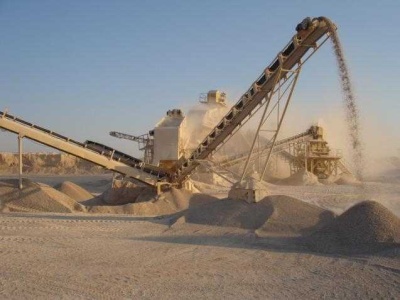
22/10/2016 · The value of the fine coal necessitated the selection of the correct equipment for the gravity beneficiation of this coal. On the other hand, fine coal might be unwanted; it all depends on the coal, the market and the decision makers. Each technology in use for the processing of fine coal therefore has its own place in the process flow diagram.

Coal dense medium separation dynamic and steadystate ...
Coal dense medium separation is a popular beneficiation process used for the upgrading of coal ore into power station and metallurgical coal. The control systems used in coal beneficiation are often limited to localised regulatory control of feed rate and medium density. A coal dense medium separation process can benefit substantially from ...


Geothermal power plant process flow diagram
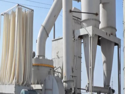
As the flue gas flow diagram of the thermal power plant shows, after the combustion process, the flue gas which has a sufficient quantity of heat is made to pass boiler tubes, dust collectors, economizers, and Preheater before passing out through a chimney.

Process Flow Diagram | Petrof Refining Technologies
Petrof Refining Technologies Level 9, Platina Bldg, Block G, Plot C59, BandraKurla Complex, Bandra (East), Mumbai – 400051 Maharastra, India. T: +91 22 6700 0569 F: +91 22 6700 0600


Typical IGCC Configuration |
Typical IGCC Configuration. While there are many coal gasifiion plants in the world producing electricity, fuels, chemicals and/or steam, the following are seven notable, commercialsize IGCC plants for producing electricity from coal and/or coke. Figure 2 shows a simplified block flow diagram (BFD) illustrating the major process sub ...