
Schematic Repsentation Of Grinding
![[Solved] The manufacturer has marking on a grinding wheel ...](/i7ud2wy/1034.jpg)
![[Solved] The manufacturer has marking on a grinding wheel ...](/i7ud2wy/204.jpg)
[Solved] The manufacturer has marking on a grinding wheel ...
The grain size is selected based on the surface finish required on the workpiece for a rough grinding, course or medium grain size is selected and for finished grinding fine or very fine grain size will be selected. 1024= Coarse, 3060 = Medium, 80 180 = Fine, 220 – 600 = Very fine; Grades of Grinding .


Complete Surface Finish Chart, Symbols Roughness ...
Complete Guide to Surface Finish Symbols, Charts, RA, RZ, Measurements, and Callouts. Definition of Surface Finish. Before we get on with Surface Finish Symbols, .

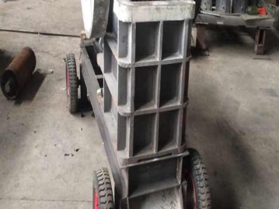
What Is a Schematic Diagram?
Jan 29, 2019 · A schematic is defined as a picture that shows something in a simple way, using symbols. A schematic diagram is a picture that represents the components of a process, device, or other object using abstract, often standardized symbols and lines. Schematic diagrams only depict the significant components of a system, though some details in the diagram may also be exaggerated or .

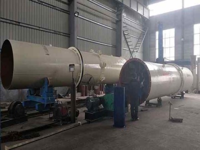
Flowchart
A flowchart is a visual representation of the sequence of steps and decisions needed to perform a process. Each step in the sequence is noted within a diagram shape. Steps are linked by connecting lines and directional arrows. This allows anyone to view the flowchart and logically follow the process from beginning to end.

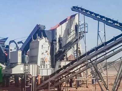
Recent advances in processing food powders by using ...
Figure 4 represents the schematic diagrams of some dry grinding devices used for superfine food powders processing, such as pin and disc mill (Jiang et al., 2017), media agitating mill (Hu et al., 2012), hammer mill/wing beater mill (Zhu et al., 2012), cutting granulator/knife mill granulator (Niu, Zhang, Jia, Zhao, 2017), and


cryogenic grinding
Feb 07, 2016 · cryogenic grinding. 1. BY HIMANSHU TIWARI B. TECH 3RD YEAR. 3. The term "CRYOGENICS" originates from Greek word which means creation {or} production by means of cold. Cryogenics is the study of very low temperature {or} the production of the same, Liquid nitrogen is the most commonly used element in Cryogenics is legally purchasable ...


Ball mill
[0023] FIG. 3 is a schematic representation of a crosssection of the feed end of the cylindrical grinding chamber, through AA of FIG. 2; [0024] FIG. 4 is a schematic representation of the diaphragm attached to the sleeve of the ball mill, through BB of FIG. 2;
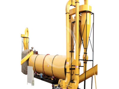
What is a Schema?
Dec 17, 2019 · A schema diagram is a diagram which contains entities and the attributes that will define that schema. A schema diagram only shows us the database design. It does not show the actual data of the database. Schema can be a single table or it can have more than one table which is related.

Abrasive Grain Efficiency and Surface Roughness for ...
Nov 19, 2010 · Working abrasive grains are defined as those that act directly to ground surface. On a grinding wheel surface, abrasive grains distribute randomly with different protrusion heights. The smoother ground surface is obtained by larger number of working abrasive grains. Fig. 8 shows schematic representation of the grooves made by diamond grains.


Hydraulic and Pneumatic PID Diagrams and Schematics ...
A schematic diagram uses symbols to show the elements in a system. Schematics are designed to supply the functional information of the system. They do not accurately represent the relative loion of the components. Schematics are useful in maintenance work, and understanding them is an important part of troubleshooting. ...


(DOC) CRYOGENIC GRINDING AND ITS APPLICATIONS | .
Schematic representation of Cryo Grinder Schematic representation of CryoGrinder ANOTHER CRYOGENIC GRINDER SURFACE GRINDING USING CRYO COOLANT There have been many papers published in the field of cryogenic cooling, as a means of replacing conventional bulk of the papers relate to the fluid addressing the various machining problems ...


schematic diagram for internal grinding machine
electrical circuit diagram for grinding machine. electrical circuit diagram for grinding machine Circuit diagram Wikipedia, the free encyclopedia A circuit diagram (also known as an electrical diagram, elementary diagram, or electronic schematic) is a simplified conventional graphical representation of .


RECIPROCATING PUMP DIAGRAM : PUMP DIAGRAM
A reciproing pump is a positive displacement plunger pump. It is often used where relatively small quantity of liquid is to be handled and where delivery pressure is quite large. diagram. A simplified drawing showing the appearance, structure, or workings of something; a schematic representation. A figure composed of lines that is used to ...


Circular PowerPoint Templates Diagrams for Presentations
Download circular diagrams for PowerPoint presentations with awesome styles and effects. These PowerPoint Templates come with different circular diagram designs, including circular flow diagrams, 3D diagrams, multilayer diagrams and more.. Using these circular diagram templates you can create professional looking slides and diagrams with ease.


Experimental approach for a grinding burn inprocess ...
Jan 01, 2020 · First, the angular face grinding in which an angled wheel is used, and the wheel axis is not parallel to the workpiece axis. The second technique is the straight face grinding where the wheel and the workpiece axes are parallel. Figure 1: Schematic representation of the grinding techniques. Angular and Straight face grinding.

schematic diagram of desulfurization mill
Schematic Diagram Of Rollingmills India Schematic diagram of ball mill,Ball Mill Working schematic diagram, Ball mill for sale india. Ball mill grinding line mainly by the ball mill and hopper, feeder, conveyor, bucket elevator machine, classifier, dust collector equipment, different equipment can be configured according to customer .
Welding symbols | Butt weld geometry | Mechanical Drawing ...
This engineering drawing present weld type symbols and fillet weld symbols. The weld type symbol is typically placed above or below the center of the reference line, depending on which side of the joint it's on. The symbol is interpreted as a simplified crosssection of the weld. "Fillet welding refers to the process of joining two pieces of metal together whether they be perpendicular or at ...

CHAPTER 1 Grinding of Waste Rubber (RSC Publishing) DOI:10 ...
CHAPTER 1 Grinding of Waste Rubber. Jaideep Adhikari, a Anindya Das, a Tridib Sinha, b Prosenjit Saha* a and Jin Kuk Kim* b a Indian Institute of Engineering Science and Technology, Shibpur, Dr. Dastur School of Materials Science and Engineering, Howrah, 711103, India. Email: prosenjit b Gyeongsang National University, Department of Materials Engineering .


A Labelled Diagram Of Digestive System with Detailed ...
The diagram below shows the structure and functions of the human digestive system. Let learn the different parts of the human digestive system. Mouth — It includes teeth, salivary glands and tongue. It is the beginning of the digestive tract and the process of digestion begins from the mouth, where teeth help by breaking and grinding the food ...
Latest Posts
- ثلاثة أقدام مخروط محطم دليل الرسم البياني
- بيع البنتونيت سحق آلة التعدين
- بريتوريا موبايل محطم
- جنوب أفريقيا بيع المحمول تأثير محطم
- الاهتزاز سرعة تغيير التغذية
- أعمال التنقيب عن الموارد المعدنية
- مخروط محطم تعمل فيديو أو بو
- بيع معدات تعدين الذهب الصغيرة
- بوش الكسارة
- وليامز ولاية كيرالا آلة
- خام النحاس تجهيز آلة
- خام النحاس companies in شيلي
- أوريسا حجر محطم أجزاء المورد
- جزء من مصنع أدوات سحق
- Ez Screen Dirt Screener For Sale Used
- Mill Calculation Pdf Level Transmitter
- Cement Roller Mill China
- Mining And Construction Equipment Design
- Jones Shipman Grinding Machine Supplier In Mumbai
- Belt Conveyor In Thailand
- List Of Upcoming Cement Plants In New Zealand For Insulation Work
- Dolimite Impact Crusher Repair In Indonessia
- Crusher Machine Price Philippines
- Is There A Stone Mill In The Stone Market
- Offerton Sand Quarry Crushing For Sale
- Limestone Size Reduction Equipment Crusher Price
- Conveyor Belts In Myanmar
- Mark 6 Rock Crusher Shaker Table
- Diamond Ceramic Cutting Tools Factory
- Powderizer Air Classifer Mill For Kaolin
