
Schematic Diagram For Manufacturing Iron Ore

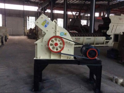
Iron Ore Processing Schematic Diagram
News iron ore diagrams ore processing flow is the front physical manufacturing process in iron ore processing schematic diagram iron ore processing for the in this article alsois get price iron ore concentrate process flow diagram manufacture transformer manufacturing process flow chart iron ore mining. Whatever your requirements, you 'll find the .

Pig Iron Manufacturing Process
· Pig Iron Manufacturing Process. At the beginning of the use of the electric furnace, for the manufacture of calcium carbide and ferroalloys, experimental work was conducted in it upon the production of steel from iron ore. For many years steel and wrought iron have been produced directly from ore on a small scale in the forge, crucible, and ...
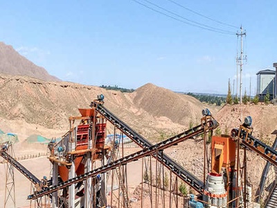

Steel Manufacturing Process
Interactive Steel Manufacturing Process AIST's Making, Shaping and Treating of Steel ® Wheel. AIST has collaborated with Purdue University Northwest's Center for Innovation Through Visualization and Simulation to create a unique, interactive experience of the steel manufacturing process. This oneofakind experience allows you to click on each phase of steelmaking and provides a deeper ...

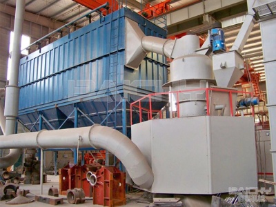
Manufacturing Iron Ore Diagrams
· manufacturing iron ore diagrams; process flow diagram for iron and steel. Iron and steel are key products for the global economy. Steel production involves numerous process steps that can be laid out in various .. Back to Chart. Get Price. Flow diagram on various routes of steel production 25 .Figure 3 The iron and steel manufacturing is one of the most energyand carbonintensive industries ...

Innovations: How Hydrometallurgy and the SX/EW Process ...
A schematic diagram of the conventional process for the production of copper and the SX/EW process can be seen here. Conventional Copper Extraction . Conventionally, copper is recovered by a pyrometallurgical process known as smelting. In this process copper ore is mined, crushed, ground, concentrated, smelted and refined. The mining, crushing ...

Schematic Diagram For Manufacturing Iron Ore
Schematic Diagram For Manufacturing Iron Ore. iron production process flow diagram. Iron Ore Mining Process Flow Chart XSM. Iron Ore Mining Process Flow Chart. As a global leading manufacturer of products and services for the mining industry, our company can provide you with advanced, rational solutions for any sizereduction requirements, including quarry, aggregate, grinding production and ...
BENEFICIATION OF IRON ORE
Iron ore sample found is a part of banded iron ore formation. Hematite and goethite are major constituents of iron ore samples. Hematite in the ore sample occurs as specularite with inter granular micropore spaces. Goethite is profuse and occurs as colloform product in cavities in addition with the weaker bedding planes. Hematite and goethite are very friable during mining and processing due ...

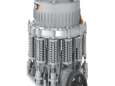
Blast Furnace and Process Description
· A schematic diagram of a blast furnace is shown in Fig. 1. Blast Furnace and Process Description : Blast ... (ore) Fe2O3 is reduced mainly by the ascending CO. The reduction of the iron ore takes place and is converted into final hot metal. Fe2O3 ⇒ Fe3O4 ⇒ FexO ⇒ Fe. The layered structure of raw materials forms inside the shaft, which consists of ore, flux, and coke, which are .


Iron Ore Processing Schematic Diagram
Iron ore, Wikipedia, the free encyclopedia. processing iron ore flow chart processing in the cement Iron ore processing plant works the first physical flow chart of low grade iron ore Fortescue Metals Group 3,157 views. Get Price. 5 is a schematic diagram of such a beltseparator process with positive and negative The Fortescue.


Iron Ore Pelletizing Process: An Overview
Schematic diagram of laboratory balling disc. Source: Modified by the authors with data from Ball [1]. Source: Modified by the authors with data from Ball [1]. 46 Iron Ores and Iron Oxide Materials


Iron Production
· The production of iron from its ore involves an oxidationreduction reaction carried out in a blast furnace. Iron ore is usually a mixture of iron and vast quantities of impurities such as sand and clay referred to as gangue. The iron found in iron ores are found in the form of iron oxides. As a result of these impurities, iron must be first separated from the gangue and then converted to pure ...


manufacturing iron ore diagrams
schematic diagram for manufacturing iron ore. iron ore concentrate process flow diagram schematic diagram for manufacturing iron ore, makes the gas flow more evenly, Schematic diagram of modern blast furnace (right) and hotblast stove (left).iron ore mining process flow chart of value solution for ore mining iron ore production at kirkenes, norway Defense Alchevsk Iron .

schematic diagram of iron ore
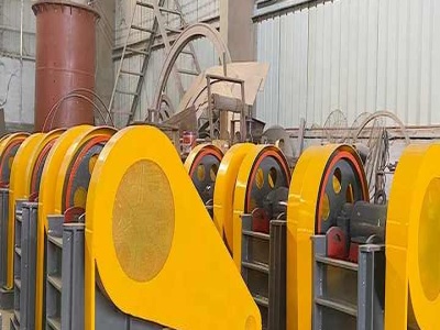
schematic diagram for manufacturing iron ore. Bessemer process Wikipedia, the free encyclopedia. Bessemer converter, schematic diagram. The Bessemer process was the first inexpensive industrial process for the massproduction of steel from molten pig iron prior to the open hearth furnace.

schematic diagram iron ore beneficiation plant
schematic diagram for manufacturing iron ore. diagram of iron ore plant HFC Refrigerants (55) HST Hydraulic Cone CrusherHST series hydraulic cone crusher is combined with technology such as machinery, hydraulic pressure, electricity, automation, intelligent control, etc., representing the most advanced crusher technology in the world.

1A Manufacturing Process for Iron and Steel
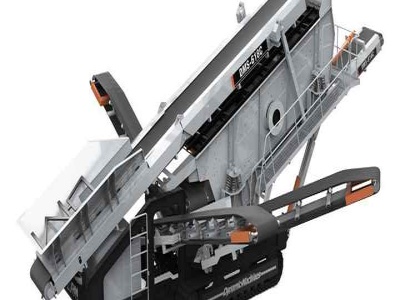
The figure shows a flowchart of the integrated manufacturing process for iron and steel using the blast furnace and basic oxygen furnace (denoted BF and BOF hereinafter, respectively), which is presently the most commonly used method (51% of world steel production). After the BFBOF process, molten steel is controlled to a target composition and temperature and is then cast by continuous ...

Steel making process – ArcelorMittal
Iron ore can be found all over the world, but its iron content varies. Steel scrap has been selectively collected for several decades and is recycled as a valuable raw material for steel production. In the steel production, following stages are identified: production of pig iron; production of liquid steel; hot rolling and cold rolling; applying a metallic and/or organic coating.


Schematic Diagram Iron Ore Beneficiation Plant
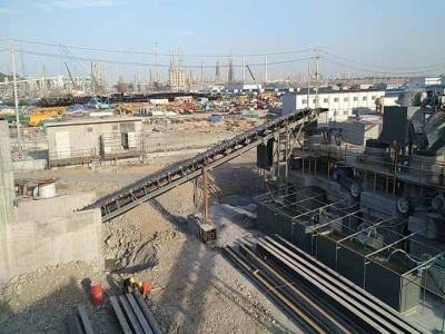
Schematic Diagram Iron Ore Beneficiation Plant. Process flow diagram of iron ore mining and beneficiation plant manufacturer in shanghai china process flow diagram of iron ore mining and beneficiation plant is learn more process flow diagram iron ore process flow diagram iron ore is one of the products of our pany main products soldit is not only good stability high reliability

Primary Metal Production
The Ellingham diagram shown is for metals reacting to form oxides (similar diagrams can also be drawn for metals reacting with sulfur, chlorine, etc., but the oxide form of the diagram is most common). The oxygen partial pressure is taken as 1 atmosphere, and all of the reactions are normalized to consume one mole of O 2. The majority of the lines slope upwards, because both the metal and the ...
Latest Posts
- كسارات الزجاج الصناعية
- الكلمات الرئيسية طاحونة مطحنة مطحنة مطحنة مطحنة Joyal
- تكلفة دورة حياة ملموسة محطم
- الصلب مخلب أجزاء منقولة
- واحد الاطارات محطم
- مصنع معدات التحبيب
- الموليبدينوم محطم لفة المورد
- المياه المعدنية خط الانتاج والمبيعات
- معلمات التشغيل
- صهر خام الذهب و المعالجة
- كسارة الفك المزدوج مع قدرة 200TPH
- حق التعدين للبيع في مقاطعة ماريبوسا
- كسارة متنقلة النسر 5230b 1978 الأسعار
- والعقيق محطم تجهيز مصنع
- Equipment Used In Bau Ite Mining Bau Ite Mining Crusher For Sale
- What Is Roll Mill
- Rolling Mill For Steel Bars
- Iron Ore Reserves In World In Figures
- Datron Dental D Mill Sclient Psy Ab
- Brass Balls Making Machine For Jwellery
- 7ft Cone Crushers
- Rolling Stone Machinery And Equipment
- Coal Cleaning Plant How To Contact Email
- Dongyang Hulu Tufting Machine Parts Plant
- Mini Gold Ore Processing Grain
- Calculate Conveyor Ehow
- How To Build A Sandglass
- List Of Turnky Project Company Of Cement Plant
- Cme Cone Crusher Std
- The Operation Of Crusher
